大家都知道GPIO是一个单片机最基础的功能模块,不管是哪个MCU平台的学习都是从GPIO驱动的闪灯程序开始,当然S32K3 也不例外。但是在S32K3 的RM中却找不到GPIO的章节,因为S32K3 的GPIO功能从属于Siul2(System Integration Unit Lite2)模块,这更像是PowerPC内核的MCU而不是上一代的S32K1。Siul2.gpio 相较来说比S32K1的配置更复杂一些,具体就是以下的文章内容。
-
所有的GPIO在硬件分为两个GPIO的电源域,VDD_HV_A 和VDD_HV_B。两个电源域的GPIO可以不同电平3.3Vt和5V,互相没有干扰,减少对电平转换芯片的使用。
-
可对同端口的多个引脚进行并行的读写操作,保证同步性。
-
共有32个GPIO外部中断IRQ,每8个引脚共用一个中断,最多16个引脚可以Link DMA请求。
-
GPIO引脚频率支持10MHz、25MHz、50MHz、210MHz,高速信号需要选用高速引脚。
-
不支持开漏输出(OD),支持Standby 模式的Pad keeping。
S32K1 的GPIO配置相对简单,只需要对PORTX.PCRn 配置,即可完成GPIO模式、上下拉等配置,再通过PTx.PDDR 做数据方向配置和PTx.PDIR/PTx.PDOR 读写控制。
S32K3相比K1差异较大,GPIO配置需要配置Siul2。MSCR(Multiplexed Signal Configuration Registe)用于输出配置,包括GPIO功能的选择(SSS)输入/输出Buffer的使能(IBE/OBE),上下拉配置等全部GPIO配置。
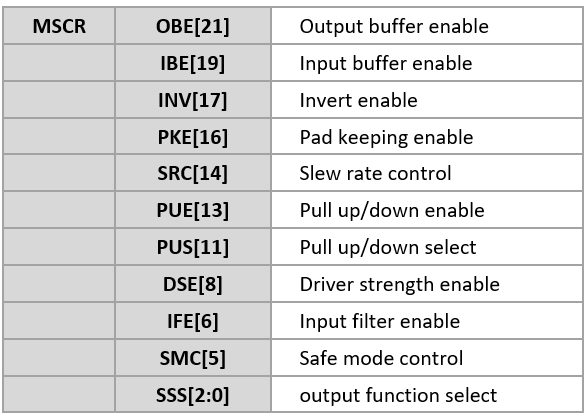
IMCR(Input Multiplexed Signal Configuration Register)用于输入配置,GPIO的输入只需要配置MSCR。配置为GPIO功能后,使能输出/输入Buffer(OBE/IBE),通过GPDOx/GPDIx/PGPDOx/PGPDIx 实现IO控制,注意OBE/IBE可同时使能,输出时可以读到输出值。
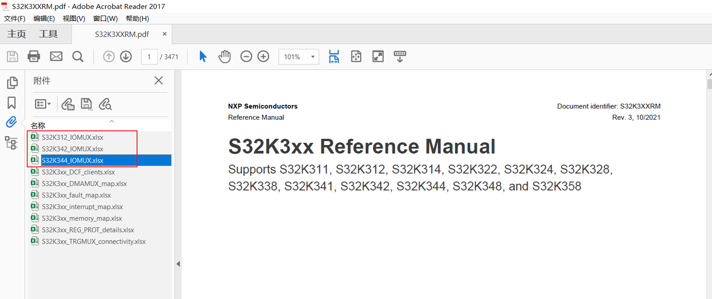
具体关于 MSCR和IMCR 详细说明,需要参考RM中附件S32K3XX_IOMUX.xlsx
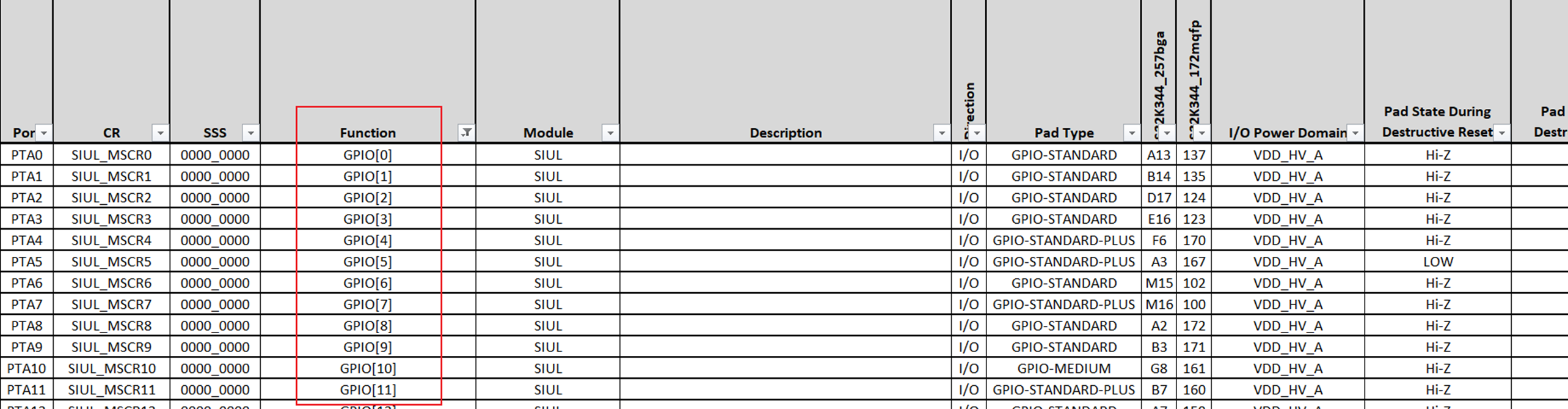
S32K3XX_IOMUX.xlsx中S32K344_IO Signal Table表如下,我们能看到所有引脚对的应的MSCR编号,Function 选择GPIO 即为GPIO 功能,GPIO功能的SSS都为0,EIRQ为外部中断功能,表中还可以看到引脚所在的电源域。
RTD 的驱动程序分为两大层:Lowlevel 层和Mcal层,都可以实现配置和驱动。
与GPIO 相关RTD Lowlevel里的模块有:
-
MCU:Mcal 基础模块,时钟、电源、RAM等配置
-
-
基于4/14/2022 最新版 D2203,包含Autosar 和NonAutosar 两个程序。
-
Dio_Example: Autosar, Mcal 层
-
Siul2_Dio_Ip_Example: NonAutosar(Lowlevel)

一. Siul2_Dio_Ip_Example Description(NonAutosar)
LED_RED - toggled using Siul2_Dio_Ip driver and configure other pins using Siul2_Port_Ip driver (Pins tool)
1.1 The application software functionality
LED control with write channel
2.1 Hardware installation
2.1.1 Supported boards
- S32K3X4EVB-Q257
- XS32K3XXEVB-Q172
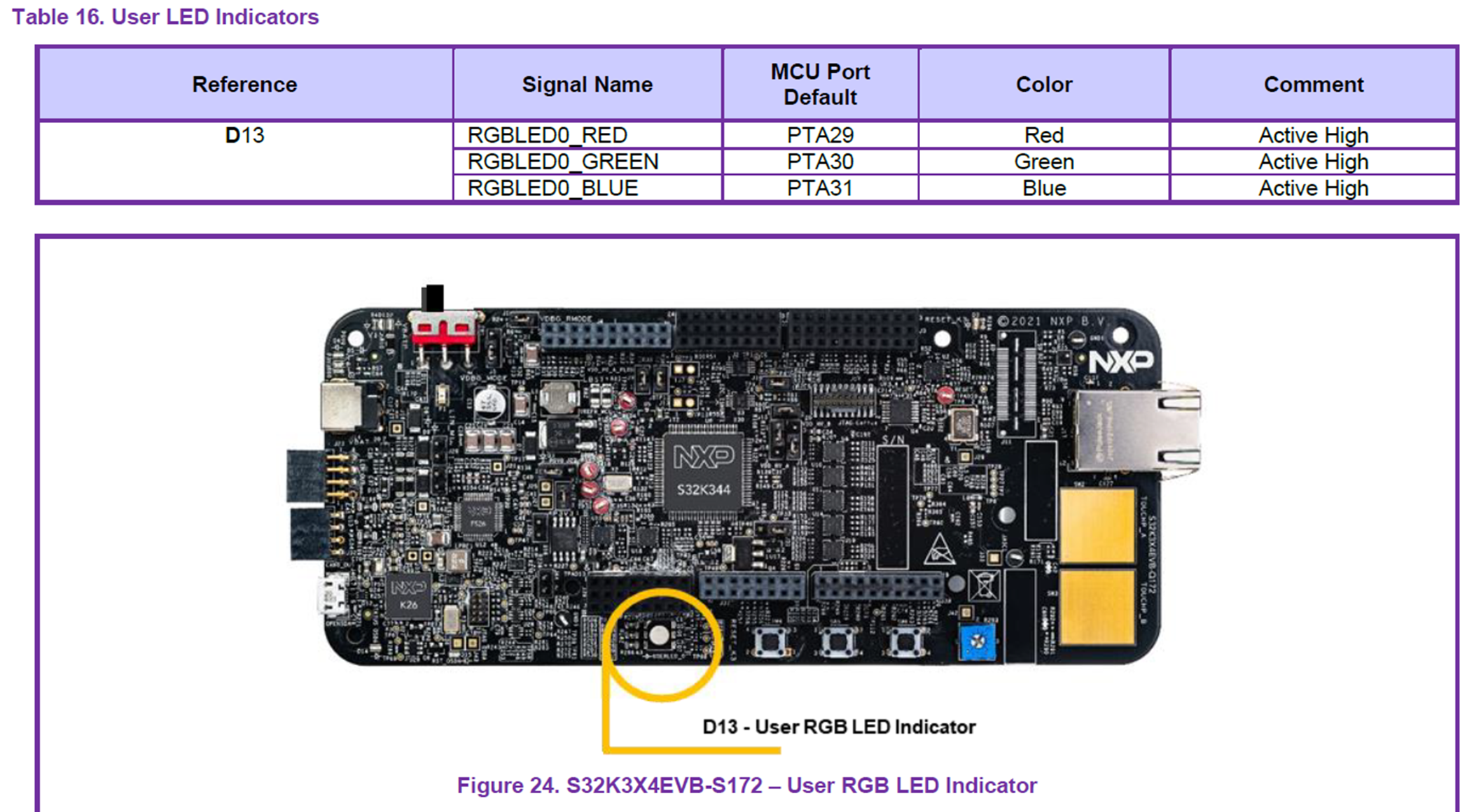
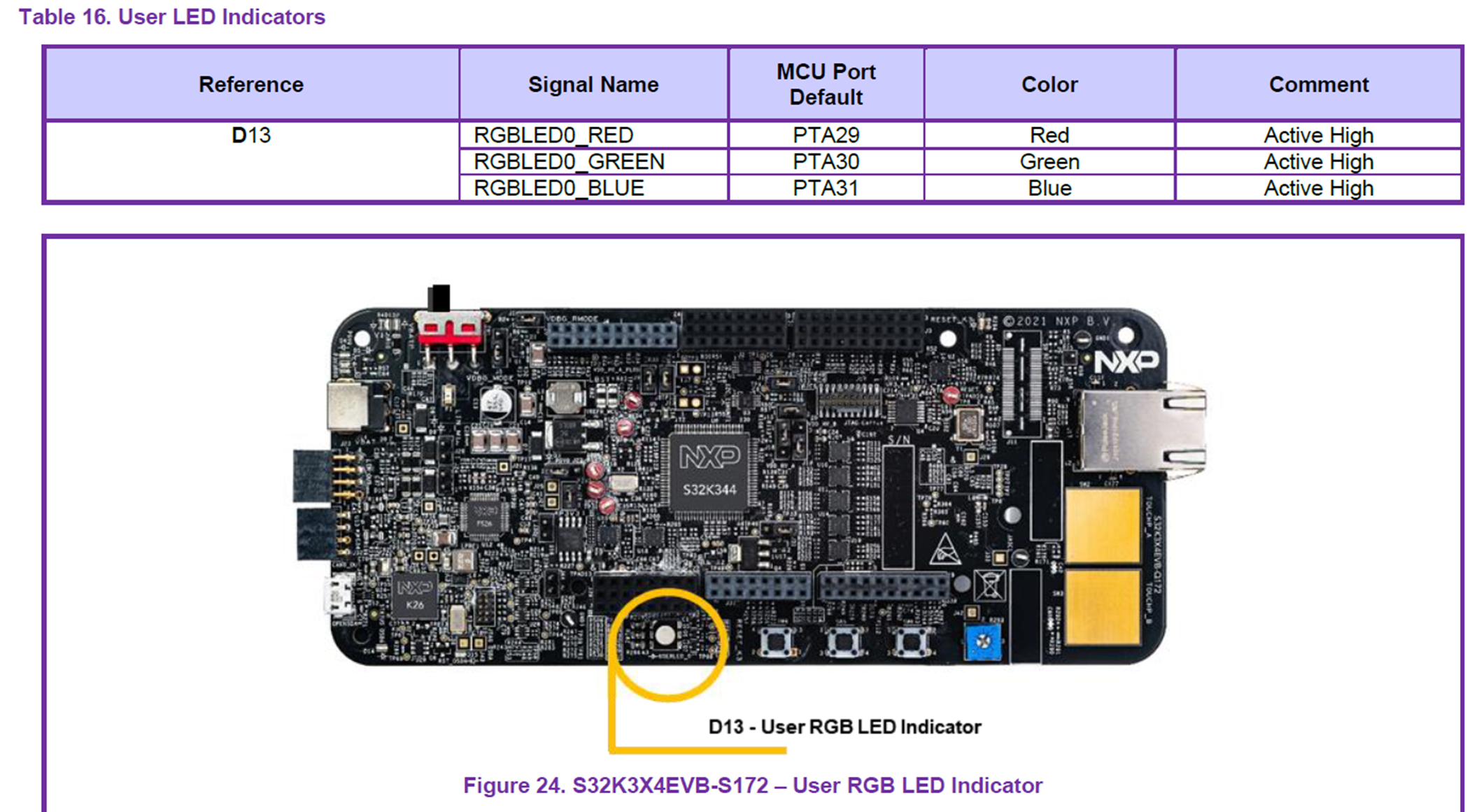
- PTA29 is controlling the LED_RED in XS32K3XXEVB-Q172 EVB board - when HIGH LED is ON when LOW LED is OFF.
- PTB18 is controlling the LED_RED in S32K3X4EVB-Q257 EVB board - when HIGH LED is ON when LOW LED is OFF.
- XS32K3XXEVB-Q172: The debugger must be connected to J12 20-pin JTAG Cortex Debug connector or J40 for openSDA.
- S32K3X4EVB-Q257: The debugger must be connected to J365 20-pin JTAG Cortex Debug connector or J55 for openSDA.
2.2 Software installation
2.2.1 Importing the S32 Design Studio project
After opening S32 Design Studio, go to "File -> New -> S32DS Project From Example" and select this example. Then click on "Finish".
The project should now be copied into your current workspace.
3. Generating, building and running the example application
3.1 Generating the S32 configuration
-
Before running the example a configuration needs to be generated. First go to Project Explorer View in S32 DS and select the current project. Select the "S32 Configuration Tool" menu then click on the desired configuration tool (Pins, Cocks, Peripherals etc...). Clicking on any one of those will generate all the components. Make the desired changes (if any) then click on the "S32 Configuration Tool->Update Code" button.
3.2 Compiling the application
-
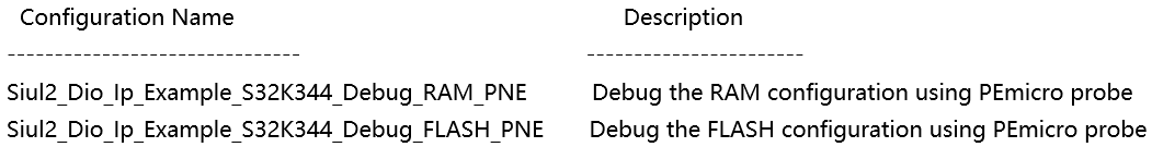
Select the configuration to be built: RAM (Debug_RAM), or FLASH (Debug_FLASH) by left clicking on the downward arrow corresponding to the build button in eclipse.
-
Use Project > Build to build the project.
-
Wait for the build action to be completed before continuing to the next step. Check the compiler console for error messages; upon completion, the *.elf binary file should be created.
3.3 Running the application on the board
-
Go to Run and select Debug Configurations. There will be a debug configuration for this project:

-
Select the desired debug configuration and click on Launch. Now the perspective will change to the Debug Perspective.
-
Use the controls to control the program flow.
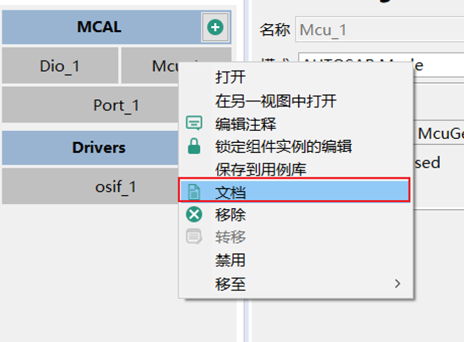
导入Siul2_Dio_Ip_Example后(导入过程省略),双击 .mex 进入CT
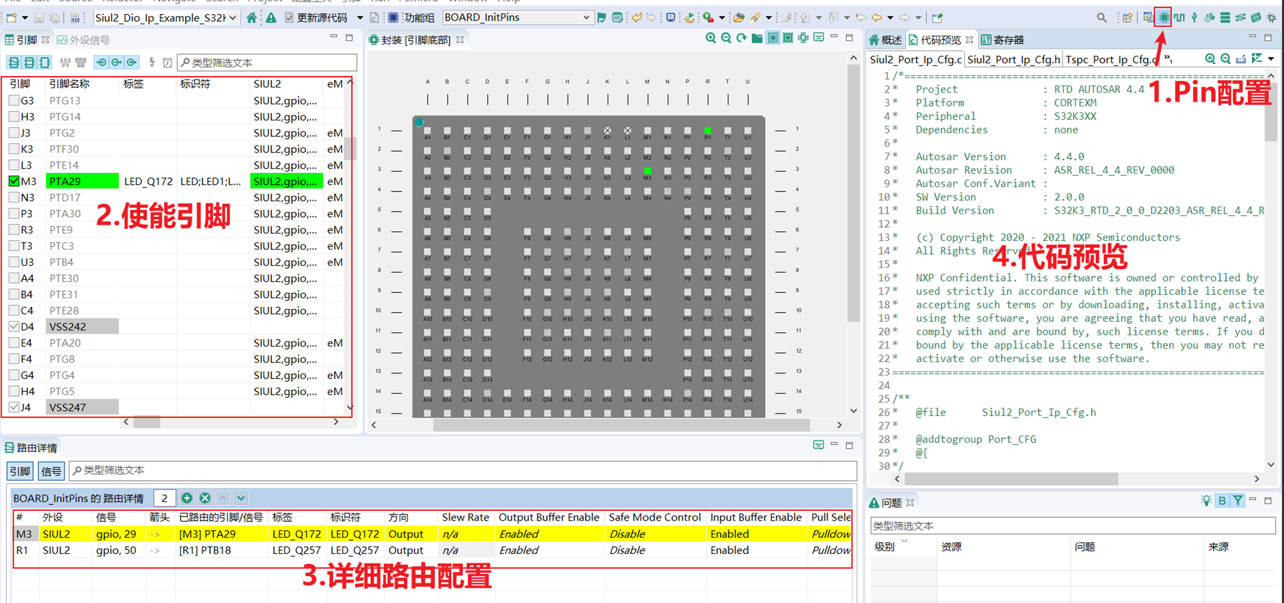
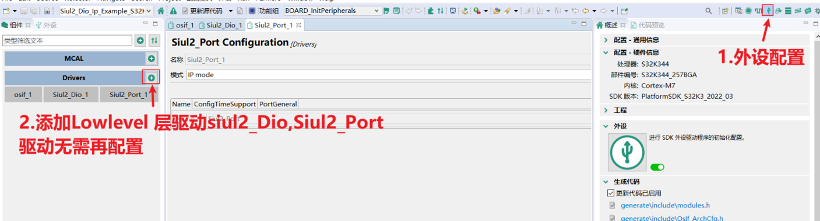
头文件导入,自行添加刚刚添加的Driver的头文件
#include "Siul2_Port_Ip.h"
#include "Siul2_Dio_Ip.h"
/* Initialize all pins using the Port driver */
Siul2_Port_Ip_Init(NUM_OF_CONFIGURED_PINS0, g_pin_mux_InitConfigArr0);
二. Dio_Example_S32K344: Autosar
LED_RED - pins configuration using Port driver and pin toggle using Dio driver.
1.1 The application software functionality
2.1 Hardware installation
2.1.1 Supported boards
- S32K3X4EVB-Q257
- XS32K3XXEVB-Q172
- PTA29 is controlling the LED_RED in XS32K3XXEVB-Q172 EVB board - when HIGH LED is ON when LOW LED is OFF.
- PTB18 is controlling the LED_RED in S32K3X4EVB-Q257 EVB board - when HIGH LED is ON when LOW LED is OFF.
- XS32K3XXEVB-Q172: The debugger must be connected to J12 20-pin JTAG Cortex Debug connector or J40 for openSDA.
- S32K3X4EVB-Q257: The debugger must be connected to J365 20-pin JTAG Cortex Debug connector or J55 for openSDA.
2.2 Software installation
2.2.1 Importing the S32 Design Studio project
After opening S32 Design Studio, go to "File -> New -> S32DS Project From Example" and select this example. Then click on "Finish".
The project should now be copied into your current workspace.
3. Generating, building and running the example application
3.1 Generating the S32 configuration
-
Before running the example a configuration needs to be generated. First go to Project Explorer View in S32 DS and select the current project. Select the "S32 Configuration Tool" menu then click on the desired configuration tool (Pins, Cocks, Peripherals etc...). Clicking on any one of those will generate all the components. Make the desired changes (if any) then click on the "S32 Configuration Tool->Update Code" button.
3.2 Compiling the application
-
Select the configuration to be built: RAM (Debug_RAM), or FLASH (Debug_FLASH) by left clicking on the downward arrow corresponding to the build button in eclipse.
-
Use Project > Build to build the project.
-
Wait for the build action to be completed before continuing to the next step. Check the compiler console for error messages; upon completion, the *.elf binary file should be created.
3.3 Running the application on the board
-
Go to Run and select Debug Configurations. There will be a debug configuration for this project:
-
Select the desired debug configuration and click on Launch. Now the perspective will change to the Debug Perspective.
-
Use the controls to control the program flow.
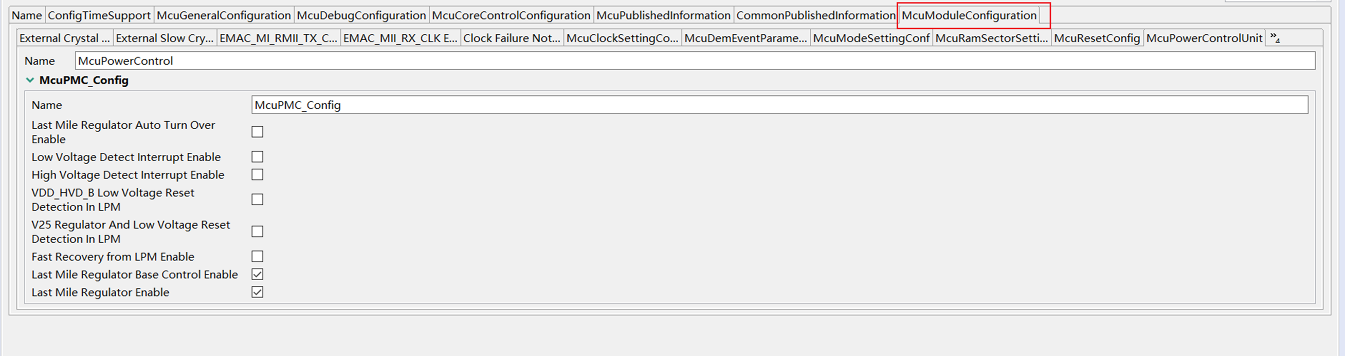
查看以下两项,对MCU模块有个大体认识,管理时钟,电源和RAM,以下是相关的硬件模块。
The MCU Driver controls the CLOCK, POWER and RAM modules of the S32K3XX device. It provides the following features:
-
Configuration and initialization of the CLOCK.
-
Configuration and initialization of the POWER.
-
Configuration and initialization of the RAM.
The MCU Driver consists of:
-
Clock IPs (FIRC, SIRC, SXOSC, FXOSC, PLL, MC_CGM, MC_ME, PRAMC, FLASH, CMU_FC, EMIOS, RTC)
-
Power IPs (MC_ME, PMC, MC_RGM, FLASH, CortexM7, DCM_GPR)
-
重点是 McuModuleConfiguration,这里保持默认,后续详解
This module provides the service for initializing the whole PORT structure of the microcontroller. Many ports and port pins can be assigned to various functionalities, e.g.:
For this reason, there is an overall configuration and initialization of this port structure. The configuration and mode of these port pins is microcontroller and ECU dependent.
Port initialisation data are written to each port as efficiently as possible. This PORT driver module completes the overall configuration and initialisation of the port structure which is used in the DIO driver module. Therefore, the DIO driver works on pins and ports which are configured by the PORT driver.
The PORT driver is initialised prior to use of the DIO functions. Otherwise DIO functions will exhibit undefined behaviour.
The hardware configured by the Port driver is SIUL2. Every PortPin configured in a PortContainer of the Port plugin can be mapped to one and only one microcontroller pin. The following steps must be followed in order to correctly map a Port plugin pin over a specific microcontroller pin:
-
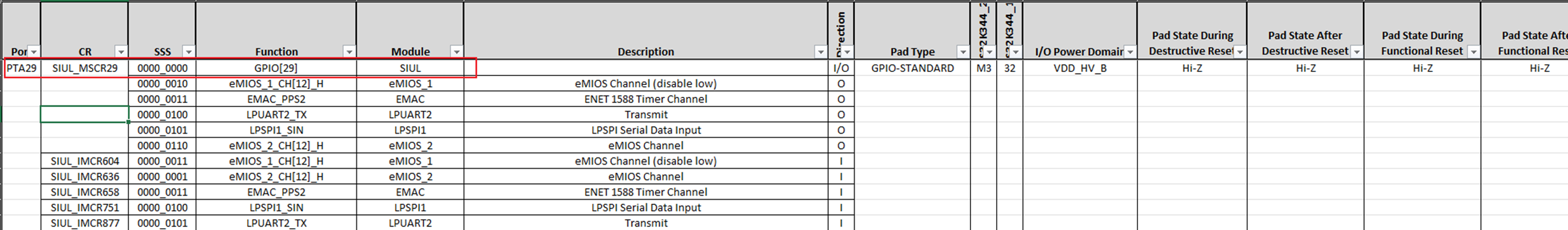
Open the S32K3xx_IOMUX Excel file attached to the Reference Manual
-
Go to 'IO Signal Table' sheet
-
Identify the microcontroller pin you want to use (eg. PTB[3]), searching after the values in columns 'Module' and 'Function'. Scroll to the Excel row where the pin's name appear first in column 'Port'. On the column 'CR' there is a number which represents the numeric value of the Multiplexed Signal Configuration Register. Note down this number (eg. 35)
-
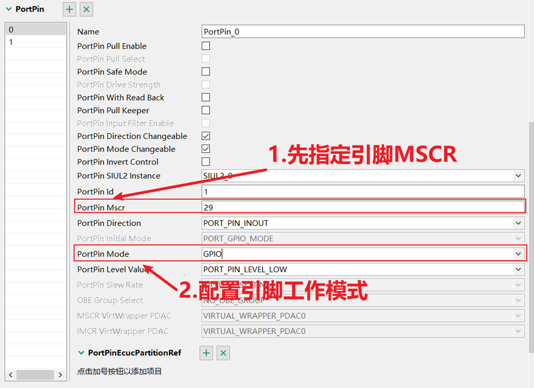
Go to port container inside the Port plugin where you want to add the pin
-
Add a new PortPin in the port container list then double click the newly added PortPin to open it's properties
-
Go to the 'PortPin MSCR' attribute and type the number noted down at step 3
-
Go to the 'PortPin Mode' attribute and choose the functionality you want to use for the selected pin
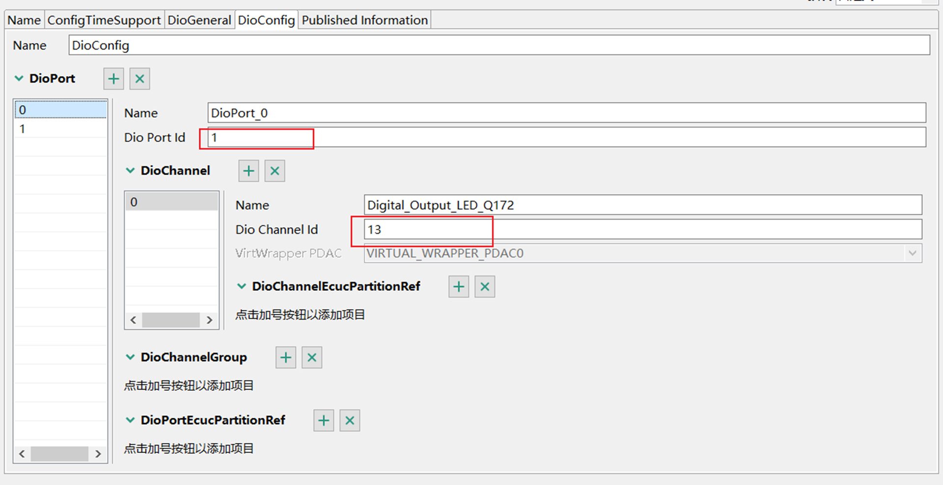
以PTA29 RED LED 为例,从IO Signal Table 中先找到 MSCR的CR 值,此处是29,PTB18 是50(S32K3X4EVB-Q257 EVB)
The DIO Driver provides services for reading and writing to/from:
-
DIO Channels (Pins)
-
DIO Ports
-
DIO Channel Groups
The behaviour of those services is synchronous. This module works on pins and ports which are configured by the PORT driver for this purpose. For this reason, there is no configuration and initialization of this port structure in the DIO Driver.
The hardware configured by the Dio driver is SIUL2. The channel to microcontroller pin mapping can be done by using the S32K3XX IO Muxing documetation Value of actual channel is identified by formula:
Channel = DioChannelId + DioPortId∗16
DioPortId is the numeric identifier of the DIO port. Symbolic names will be generated for each port pin id for the pins which being used for configuration.
– Port AL=0
– Port AH=1
– Port BL=2
– Port BH=3
– Port CL=4
– Port CH=5
– Port DL=6
– Port DH=7
– Port EL=8
– Port EH=9
– Port FL=10
– Port FH=11
– Port GL=12
– Port GH=13
– Port AL=0
– Port AH=1
– Port BL=2
– Port BH=3
– Port CL=4
– Port CH=5
– Port DL=6
– Port DH=7
– Port EL=8
– Port EH=9
– Port AL=0
– Port AH=1
– Port BL=2
– Port BH=3
– Port CL=4
– Port CH=5
– Port DL=6
– Port DH=7
– Port EL=8
– Port EH=9
– Port AL=0
– Port AH=1
– Port BL=2
– Port BH=3
– Port CL=4
– Port CH=5
– Port DL=6
– Port DH=7
– Port EL=8
– Port EH=9
– Port AL=0
– Port AH=1
– Port BL=2
– Port BH=3
– Port CL=4
– Port CH=5
– Port DL=6
– Port DH=7
– Port EL=8
– Port EH=9
DioChannelId is selected channel in the port what is selected by choosing the value of DioPortId. The maximum channel in 1 port is 16, so the range of DioChannelId is: 0-15
Port Id:AH =1, 按下方
Dio Channel Id=29-16=13
Channel=DioChannelId + DioPortId∗16 = 13+1*16=29
– Port AL=0
– Port AH=1
– Port BL=2
– Port BH=3
– Port CL=4
– Port CH=5
– Port DL=6
– Port DH=7
– Port EL=8
– Port EH=9
– Port FL=10
– Port FH=11
– Port GL=12
– Port GH=13

清楚了官方Demo程序并不代表你对模块熟悉,还需要从空工程开始写一个有目标功能的程序,下一篇我们从头开始创建MySiul2, MyDio, MySiul2_icu。


 MyArrow™ — 艾睿电子线上系统